Table of Contents >> Show >> Hide
- Quick Reality Check: Not Every Motor Is Meant to Reverse
- The Core Idea (In Plain English)
- Tools and Materials You’ll Want Nearby
- How to Reverse an Electric Motor: 11 Steps
- Step 1) Confirm the load can run in reverse
- Step 2) Identify the motor type (this determines the reversal method)
- Step 3) Read the wiring diagram and document everything
- Step 4) Plan your reversal approach (based on motor type)
- Step 5) Lock out power and verify it’s dead (and discharge stored energy)
- Step 6) Reverse a three-phase AC motor (the easiest win)
- Step 7) Reverse a reversible single-phase AC motor (start winding swap, not line swap)
- Step 8) Add forward/reverse control (drum switch or reversing contactor)
- Step 9) Reverse a brushed DC motor (polarity, DPDT, or H-bridge)
- Step 10) Button it up, then test rotation safely
- Step 11) Troubleshoot if it doesn’t reverse (or it sounds angry)
- Common Mistakes (So You Don’t Star in Them)
- When to Call a Pro (Worth It)
- Field Notes: 500+ Words of Real-World “Experience” (The Stuff People Learn the Hard Way)
- Final Thoughts
Need your motor to spin the other way? You’re in good company. People reverse motors for everything from correcting a fan that’s blowing the “wrong” direction to fixing a conveyor that suddenly wants to moonwalk. The trick is that “reverse an electric motor” doesn’t mean one single wiring moveit depends on the motor type (single-phase AC, three-phase AC, brushed DC, stepper, brushless/EC, etc.), and whether the motor was designed to be reversible in the first place.
This guide walks you through 11 practical steps (with examples and “don’t-do-that” warnings) so you can reverse rotation safely, test correctly, and avoid turning a simple fix into a smoke machine.
Quick Reality Check: Not Every Motor Is Meant to Reverse
Before you grab a screwdriver, make sure reversing won’t damage the equipment. Some loads are direction-sensitive: certain pumps, fans with pitched blades, compressors, gearboxes, and anything with left-hand threads can loosen, leak, or self-destruct if you run it backwards. If the machine has an arrow label for rotation, believe it.
The Core Idea (In Plain English)
- Three-phase AC motors: swapping any two of the three power leads reverses rotation.
- Most reversible single-phase AC motors: you reverse the start winding leads (not the main power leads).
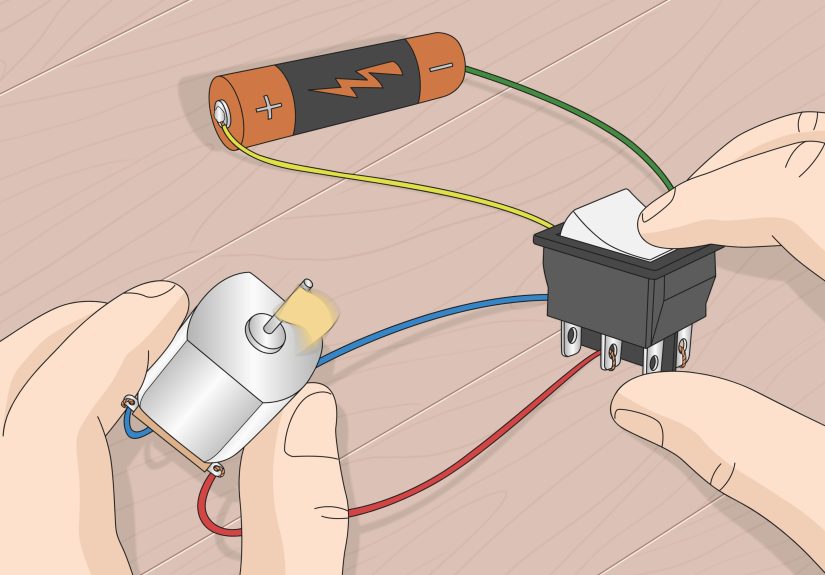
- Brushed DC motors (permanent magnet): reversing polarity reverses direction.
- Brushless DC / EC motors: direction is usually controlled by the controller, not by swapping wires.
- Steppers: swap one coil pair polarity (or change the driver’s direction signal).
Tools and Materials You’ll Want Nearby
- Multimeter or voltage tester (rated appropriately for the system)
- Insulated screwdrivers/nut drivers
- Wire labels or masking tape + marker
- Camera/phone (photos save friendships)
- Wiring diagram/nameplate info (on the motor or inside the junction box cover)
- If installing a reversing control: DPDT switch, drum switch, or reversing contactor setup (as appropriate)
How to Reverse an Electric Motor: 11 Steps
-
Step 1) Confirm the load can run in reverse
Check the machine/manual for a rotation arrow or direction note. If it’s a fan or pump, look at blade pitch or impeller design. For belt-driven systems, confirm pulley threading and set-screw orientation won’t loosen when reversed.
Example: A dust collector blower may still “spin” backwards just fine, but airflow drops dramatically because the blades are pitched for one direction. A positive-displacement pump might not be “fine” at allit can bind, cavitate, or pop seals.
-
Step 2) Identify the motor type (this determines the reversal method)
Use the nameplate and the wiring diagram. Common types you’ll see:
- Three-phase AC induction motor: typically has 3 power leads (or 9/12 leads for multi-voltage).
- Single-phase AC motor: common in homes/shops; may be split-phase, capacitor-start, capacitor-run (PSC), shaded pole.
- Brushed DC motor: often two main leads; may have field leads on wound-field designs.
- Brushless DC (BLDC) / EC motor: often 3 motor phases plus a controller module; sometimes multiple small control wires.
- Stepper motor: 4, 6, or 8 leads, usually used with a driver board.
If the nameplate says something like “CW/CCW reversible” or shows a lead-swapping note, that’s your green light. If it’s a shaded-pole motor (common in very small fans), it may be effectively non-reversible without modifications.
-
Step 3) Read the wiring diagram and document everything
Take clear photos of:
- the motor nameplate
- the wiring diagram (often under the junction box cover or on the nameplate)
- the existing lead connections and any jumpers
Then label wires before moving anything. This is the difference between “quick fix” and “mystery novel.”
-
Step 4) Plan your reversal approach (based on motor type)
Choose the correct technique:
- Three-phase AC: swap any two incoming line leads (L1/L2/L3) at the motor starter or motor junction box.
- Single-phase AC (reversible designs): swap the designated start winding leads (often specific numbered leads like T5/T8, or a pair of colored wires).
- Brushed DC (permanent magnet): reverse the two supply leads (use a DPDT switch or H-bridge if you want a control).
- DC wound-field: reverse either the armature leads or the field leadstypically not both, or you’ll end up right where you started.
- BLDC/EC: use the controller’s reverse input/parameter or a compatible controller; do not guess by swapping wires.
- Stepper: reverse one coil pair polarity (or flip DIR logic on the driver).
-
Step 5) Lock out power and verify it’s dead (and discharge stored energy)
Turn off power at the correct disconnect/breaker. Apply lockout/tagout if you’re in a shop environment. Then verify with a meter that the circuit is de-energized.
Important: Many single-phase motors have capacitors that can store energy even after power is removed. Follow safe discharge procedures (and give it time). If you’re not trained/qualified to work around stored electrical energy, stop here and bring in a qualified electrician.
-
Step 6) Reverse a three-phase AC motor (the easiest win)
For a standard three-phase induction motor, reversal is straightforward:
- Open the starter or motor junction box (power verified off).
- Choose any two of the three phase conductors.
- Swap them (for example, swap L1 and L2).
- Re-tighten terminals to the proper torque, inspect insulation, close the box.
Example: If a conveyor runs backward after a maintenance shutdown, swapping two phases at the motor starter usually fixes it in minutes.
If the motor is controlled by a VFD/drive, you can often reverse using the drive’s parameters or a digital input (preferred), but swapping motor output leads can also reverse directionjust be mindful of feedback devices (encoders) and configured rotation checks.
-
Step 7) Reverse a reversible single-phase AC motor (start winding swap, not line swap)
This is where people get tricked. On most single-phase motors, swapping the incoming hot/neutral does not reverse the motor. Direction is determined by the relationship between the run winding and the start winding.
If the motor is designed to reverse, the diagram will tell you which leads to swap. Common patterns include:
- Swapping two numbered leads (often something like “interchange T5 & T8”)
- Swapping a pair of colored leads labeled “REV” or “CW/CCW”
- Moving a jumper from one terminal to another (less common, but it happens)
Pro tip: If you don’t have a diagram and the leads aren’t clearly marked, do not “trial and error” a capacitor-start motor. Incorrect wiring can cause overheating, a loud hum, tripped breakers, or capacitor damage.
-
Step 8) Add forward/reverse control (drum switch or reversing contactor)
If you need to reverse direction regularly (lathe, winch, sander, actuator), consider a proper control method:
- Single-phase reversible motor: a drum switch or purpose-built reversing switch that swaps the start winding leads. Choose a switch rated for the motor’s voltage and current.
- Three-phase motor: a reversing starter uses two contactors with electrical/mechanical interlocks so you can’t energize forward and reverse at the same time.
- VFD-controlled systems: use the drive’s forward/reverse command input and acceleration/deceleration ramps for smoother direction changes.
Safety note: Reversing while the motor is still spinning at speed can be hard on contactors, gearboxes, couplings, and your nerves. Build in a stop-and-confirm logic or a delay, especially for heavier loads.
-
Step 9) Reverse a brushed DC motor (polarity, DPDT, or H-bridge)
For a permanent-magnet brushed DC motor, direction reversal is usually as simple as reversing polarity: swap the positive and negative leads, and the motor spins the other way.
If you want a switchable setup:
- Manual control: wire a properly rated DPDT switch in a polarity-reversing configuration.
- Electronic control: use an H-bridge motor driver sized for the motor’s stall current (not just the “running” current).
Example: For a 12V gearmotor running a small gate, an H-bridge plus limit switches can reverse direction reliablywithout you playing “hot potato” with wires.
For wound-field DC motors, reversal can be more nuanced. In many cases you reverse either the field winding polarity or the armature polarity (depending on the motor design and application). If that sentence felt like a blur, call someone who speaks fluent DC motor.
-
Step 10) Button it up, then test rotation safely
Before re-energizing:
- Confirm all connections are tight and insulated.
- Confirm the junction box cover is back on (yes, really).
- Ensure the motor shaft and load can rotate freely.
Start with a quick “bump test” (brief start/stop) to confirm direction, then run unloaded if possible. Watch for abnormal vibration, grinding, excessive current draw, or overheating.
-
Step 11) Troubleshoot if it doesn’t reverse (or it sounds angry)
If something’s off, use this quick checklist:
- Motor hums but won’t start: possible start circuit issue, incorrect single-phase wiring, bad capacitor, or mechanical binding.
- Breaker trips instantly: short, miswire, damaged insulation, or incorrect connection for the voltage.
- Direction didn’t change: you swapped the wrong wires (common on single-phase); or on DC wound-field you reversed both field and armature.
- Runs backward but weak/no torque: wrong winding relationship, incorrect capacitor connection, or load mismatch.
- VFD faults on reverse: parameter limits, rotation check, acceleration/deceleration too aggressive, or feedback configuration conflicts.
If you can’t clearly trace wiring back to a nameplate diagram (or you see scorched insulation), stop and get professional help. Electricity is not a hobby when it’s connected to 240V and a spinning chunk of metal.
Common Mistakes (So You Don’t Star in Them)
1) Swapping hot and neutral on single-phase and expecting miracles
Most single-phase induction motors don’t reverse that way. The reversal is usually done by swapping the start winding leads (if the motor supports it).
2) Ignoring the capacitor
Capacitors can store energy after shutdown. Treat them with respect and follow safe practices. “It’s unplugged” is not a discharge procedure.
3) Reversing under load with no stop logic
Slamming a motor from forward to reverse can create huge stress (electrical and mechanical). Use a stop, coast, or rampespecially with contactors and heavy inertia loads.
4) Assuming brushless motors reverse by swapping any two wires
Brushless/EC motors often require controller-level direction control. Random wire swapping can confuse commutation, trip protection, or damage electronics.
When to Call a Pro (Worth It)
- You don’t have a wiring diagram and the lead markings are unclear
- The motor is on 240V/480V in a commercial environment and you’re not qualified for that work
- It’s a critical machine (compressor, pump system, safety-related equipment)
- You suspect capacitor issues, insulation damage, or repeated breaker trips
- The motor is controlled by a VFD and reverse requires parameter and safety integration
Field Notes: 500+ Words of Real-World “Experience” (The Stuff People Learn the Hard Way)
Ask ten technicians about reversing motors and you’ll get twelve storiesbecause somebody always “just swapped two wires” and then acted surprised when the motor did something dramatic. One common experience: the motor reversal was easy, but the machine wasn’t meant to run backwards. For example, a shop might reverse a motor to fix an airflow issue, only to realize the fan blades were pitched for one direction. The motor spins, surebut the fan behaves like it’s trying to cool the room with disappointment. The fix ends up being mechanical (blade orientation or correct fan rotation), not electrical.
Another classic: the “mystery single-phase motor.” Someone opens the junction box expecting three tidy leads and finds a handful of numbered conductors, wire nuts, and what looks like a tiny soda can (the capacitor). The best experience-based advice here is boring but golden: take photos before you touch anything. People who skip that step often spend the next hour asking, “Wait… was T5 tied to T2, or T8 tied to T3?” The motor doesn’t care about your confidence. It only cares about correct connections and proper voltage.
Then there’s the “reverse switch” adventure. Folks frequently install a drum switch or DPDT setup and forget that reversing controls need to be properly rated for the current and duty. A cheap switch might work for a small DC motor on a bench but fail quickly on a bigger AC motorespecially during starts, where current can spike. The experience lesson: size components for starting and stall conditions, not just “it runs at 6 amps.”
In three-phase land, the stories are usually happier because reversing is straightforwarduntil it isn’t. A common real-world scenario: the motor is on a VFD and the tech swaps two motor leads to reverse direction, only to find the system now throws a fault when reverse is commanded. Why? Because modern drives and control systems may use rotation checks, feedback devices, or safety logic that expects a certain phase sequence and direction relationship. The fix might be as simple as changing a drive parameter or swapping direction logic in the controller instead of moving power conductors.
One more experience worth sharing: the “it hums but won’t go” moment. This happens a lot when single-phase motors are miswired or when the start circuit (capacitor or centrifugal switch) isn’t doing its job. People panic, but experienced hands do three calm things: they cut power, verify the motor is free to spin, then compare every lead connection to the nameplate diagram. If the diagram says interchange two specific leads to reverse, they do exactly thatno improvisation. If the capacitor looks bulged or leaky, they stop and replace it with the correct rating.
Finally, experienced techs develop a habit that seems almost superstitious: they “bump test” direction first. Instead of committing to a full start, they briefly energize the motor just long enough to see rotation. This tiny habit prevents big embarrassmentlike reversing a conveyor and launching product in the wrong direction, or spinning a threaded arbor in a way that loosens a nut. The motor reversal might be electrical, but the success is often behavioral: slow down, verify, then run.
Final Thoughts
Reversing an electric motor is usually one of the fastest “big wins” in troubleshootingwhen you match the method to the motor type. Three-phase? Swap any two phases. Reversible single-phase? Swap the start winding leads per the diagram. Brushed DC? Reverse polarity (with a proper control setup). And if the motor has a controller (VFD, BLDC/EC electronics), the cleanest reversal often happens in settings and control logicnot by guessing with wires.