Table of Contents >> Show >> Hide
- Introduction: The 90° Overhang Problem Nobody Invited to the Party
- What Is a 90° Overhang in FDM 3D Printing?
- What Is Non-Planar Slicing?
- How Non-Planar Slicing Makes 90° Overhangs Possible
- Why This Is Not Yet a One-Click Feature
- Practical Benefits of Non-Planar Overhang Printing
- Where 90° Non-Planar Overhangs Make Sense
- Settings That Still Matter: Cooling, Speed, Layer Height, and Flow
- Specific Example: Printing a Small Supportless Shelf
- Design Tips for 90° Overhangs With Non-Planar Slicing
- Common Problems and How to Think About Them
- The Future of Non-Planar Slicing
- Experience Notes: What It Feels Like to Work With 90° Non-Planar Overhangs
- Conclusion: Non-Planar Slicing Does Not Break the RulesIt Rewrites the Path
Note: This article is written for makers, engineers, and curious 3D printing users who already know the familiar “supports or sadness” problem and want to understand how non-planar slicing changes the rules.
Introduction: The 90° Overhang Problem Nobody Invited to the Party
Every FDM 3D printer owner eventually meets the same villain: the overhang. It looks harmless in CAD. It previews beautifully in the slicer. Then the printer starts laying molten plastic into open air, and suddenly your elegant bracket looks like it sneezed spaghetti.
The classic advice is simple: if an overhang is too steep, add supports. Supports are the training wheels of FDM printing. They work, but they also consume filament, increase print time, scar the underside of parts, and turn post-processing into a tiny archaeology project. For a normal planar slicer, a true 90° overhang is basically a horizontal shelf. There is no layer underneath the new extrusion line, so the nozzle is asked to perform a magic trick: deposit plastic where nothing exists.
Non-planar slicing offers a much more interesting answer. Instead of forcing every layer to be a flat pancake, non-planar slicing lets the toolpath rise and fall in three-dimensional curves or tilted surfaces. In other words, the printer stops behaving like a stack of paper and starts behaving more like a pen moving across a sculpted surface. That shift can improve surface finish, reduce stair-stepping, strengthen certain geometries, and, most excitingly, make extreme supportless overhangs possible in cases that would normally be considered slicer heresy.
So can you really 3D print 90° overhangs with non-planar slicing? Yes, with important caveats. This is not a universal “delete all supports forever” button. It is a toolpath strategy that depends on geometry, nozzle clearance, cooling, extrusion control, slicer workflow, and the patience level of the human currently staring at G-code previews like they are reading ancient runes.
What Is a 90° Overhang in FDM 3D Printing?
In everyday FDM terms, an overhang is any section of a model that extends outward without enough material directly beneath it. A gentle slope is usually fine because each new line still overlaps the previous layer enough to stay supported. A steep slope becomes risky because the bead has less foundation. At 90°, the feature becomes horizontal, like the underside of a shelf, ledge, hook, duct, or bracket.
The common design rule says that most FDM printers can handle roughly 45° overhangs without supports. That rule is not physics carved into stone; it is a practical shortcut. A well-tuned printer with PLA, strong part cooling, slow overhang speeds, and good layer bonding may go steeper. PETG may droop more. ABS may curl. Tiny overhangs often behave better than big ones. A short bridge between two anchor points can succeed where a wide unsupported ceiling fails. Still, the closer an overhang gets to horizontal, the more traditional planar slicing struggles.
Why Normal Planar Slicing Struggles
Planar slicing cuts a model into flat horizontal layers. The nozzle prints one layer, moves up by a fixed or adaptive layer height, and prints the next. This is efficient, predictable, and perfect for millions of parts. But it creates a “2.5D” manufacturing habit: the printer builds upward in stacked slices rather than freely following a true 3D surface.
For a 90° overhang, each new layer wants to extend beyond the layer below. The slicer may classify those lines as overhang perimeters or bridges, but it cannot change the fact that the extrusion is poorly supported. The bead may sag, curl, detach, or create rough undersides. Supports solve this by placing temporary material below the overhang, but they bring the usual baggage: waste, time, contact marks, and the delightful sound of pliers snapping tiny support towers at midnight.
What Is Non-Planar Slicing?
Non-planar slicing is a 3D printing approach where toolpaths are not restricted to flat XY layers. The Z-axis can move while the nozzle is also moving in X and Y, producing curved, tilted, or conformal paths. Instead of printing only flat layers, the printer can lay down material along surfaces that better match the model’s shape.
The concept is especially attractive for three reasons. First, it can reduce the staircase effect on shallow curved surfaces. Second, it can orient filament paths more intelligently for strength or surface quality. Third, it can create supportless features by changing how the material is accumulated. For overhangs, the key idea is not to print a horizontal ceiling all at once, but to grow the geometry through tilted or curved layers that remain better supported as they extend outward.
Planar vs. Non-Planar Layers
Imagine building a hill with flat sheets of cardboard. From the side, the hill becomes a staircase. That is planar slicing. Now imagine wrapping flexible strips over the hill’s contour. The strips follow the surface more naturally. That is the spirit of non-planar slicing.
For 90° overhangs, the difference becomes even more dramatic. A planar slicer sees a horizontal shelf and thinks, “We need support material.” A non-planar strategy may instead generate a series of angled paths that gradually project outward, letting each strand lean on the previous structure. It is less like stacking pancakes and more like building a ramp, shell, or cone-shaped growth pattern.
How Non-Planar Slicing Makes 90° Overhangs Possible
Supportless 90° overhangs with non-planar slicing usually rely on one major principle: the layer direction changes so the printer is not simply extruding into empty space. In conic or inclined slicing methods, layers can be generated around a tilted or curved slicing surface. The overhang is built outward through geometry that gives each new extrusion line some neighboring material to bond to.
One example is conic slicing, where the generated layers resemble sections of a cone rather than flat planes. This can help create overhangs because the deposited paths are angled in a way that changes the relationship between the nozzle, the part, and gravity. Instead of a straight horizontal underside, the toolpath can form a progressive structure that approaches a 90° projection while keeping the extrusion better supported.
Another related approach is mixed slicing. A model may use ordinary planar layers for most of the part, then switch to non-planar layers only where they are beneficial. This matters because fully non-planar printing is hard. Collision avoidance, nozzle geometry, and toolpath generation quickly become complicated. A hybrid workflow lets makers use normal slicing where it is efficient and reserve the fancy gymnastics for overhangs, curved surfaces, or cosmetic regions.
The Secret Ingredient: Toolpath Direction
When people discuss overhangs, they often focus only on angle. But toolpath direction also matters. A line printed parallel to the overhang edge may behave differently from one printed perpendicular to it. Non-planar slicing gives the slicer more freedom to decide where the bead goes and how it gets there. That can reduce sagging because the extrusion is not asked to span unsupported space in the same way.
Think of it like laying bricks. If you stack bricks straight up and then suddenly extend them sideways, the structure fails quickly. But if each brick overlaps and shifts gradually, the wall can curve, lean, or cantilever much farther. Non-planar slicing is not exactly bricklaying, but the analogy helps: the path strategy changes how load, adhesion, and geometry work together.
Why This Is Not Yet a One-Click Feature
If non-planar slicing is so clever, why is everyone not using it already? Because the nozzle is not a magical floating dot. It is attached to a heater block, fan duct, probe, sock, and sometimes a bulky hotend assembly that has the spatial grace of a shopping cart with one bad wheel.
Collision avoidance is one of the biggest challenges. In planar printing, the nozzle tip usually stays above the previously printed layer at a predictable height. In non-planar printing, the nozzle may travel close to raised surfaces. If the toolpath does not account for the full printhead shape, the nozzle, fan shroud, or probe can crash into the part. This is why long nozzles, compact toolheads, modified cooling ducts, and careful simulation are common in experimental non-planar printing.
Hardware Limitations
Most desktop FDM printers have three linear axes: X, Y, and Z. They can move the nozzle in 3D space, but the nozzle itself usually remains vertical. That limits how steeply the printer can follow a curved surface before the side of the nozzle or hotend interferes with the print. Multi-axis printers, such as 4-axis or 5-axis systems, can rotate the part or toolhead, making conformal printing more flexible. However, those machines are more complex and less common in hobby workflows.
For a normal Cartesian or CoreXY printer, non-planar overhang printing is possible only within a safe clearance envelope. The model must be designed or segmented so the toolhead can reach the path without smashing into already printed features. The slicer must also manage Z movement smoothly, because sudden height changes can create inconsistent extrusion, poor bonding, or surface artifacts.
Software Limitations
Traditional slicers are optimized for planar layers. They are fast, robust, and full of features like infill, supports, seams, ironing, modifiers, and adaptive layer height. Non-planar slicing asks different questions: What surface should the nozzle follow? Where can the toolhead move safely? How should extrusion flow change when path spacing varies? When should the print switch between planar and non-planar sections?
Experimental tools and research slicers have shown impressive results, but mainstream adoption remains gradual. This is normal. Slicing is not just drawing lines; it is manufacturing planning. A slicer must generate paths that are geometrically valid, mechanically printable, thermally sensible, and understandable to firmware. That is a lot to ask from software that users also expect to handle a dragon figurine, a phone stand, and a replacement dishwasher clip before lunch.
Practical Benefits of Non-Planar Overhang Printing
The most obvious benefit is reduced support material. Printing a 90° overhang without supports can save filament and shorten post-processing. It can also improve the underside appearance because there is no rough support interface to remove. For functional parts, eliminating supports can preserve fine features and reduce dimensional cleanup.
Non-planar paths can also improve surface quality. Curved top surfaces printed with flat layers show visible stair-steps, especially at shallow angles. Non-planar toolpaths can follow the surface more closely, producing smoother finishes without simply lowering layer height across the entire print. That means better quality where it matters without turning the whole job into a 19-hour meditation exercise.
There may also be strength advantages. FDM parts are anisotropic, meaning strength depends on print direction and layer bonding. If non-planar paths can align material more closely with stress paths or part geometry, certain components may perform better. This is especially interesting for brackets, ducts, shells, ergonomic parts, aerodynamic shapes, and lightweight structures.
Where 90° Non-Planar Overhangs Make Sense
Not every model deserves a non-planar workflow. For a simple part where supports are hidden and easy to remove, ordinary slicing may be faster. But non-planar overhang strategies are worth exploring when the underside matters, supports are hard to remove, material waste is costly, or the geometry is thin and delicate.
Good Candidate Parts
Good candidates include small brackets with exposed undersides, curved ducts, fan shrouds, architectural models, artistic shells, display parts, lightweight cantilevers, and experimental mechanical components. Parts with smooth transitions usually work better than parts with sudden cliffs, deep pockets, or tall obstacles near the toolpath.
Models designed specifically for non-planar printing perform best. A design that is hostile to a planar slicer may still be hostile to a non-planar slicer if the printhead cannot physically reach the area. The best results come from designing with the toolpath in mind: gradual transitions, clean clearance, controlled overhang lengths, and geometry that allows the nozzle to move without interference.
Poor Candidate Parts
Poor candidates include models with tight internal cavities, tall walls surrounding the overhang, complex organic details near the toolhead path, or geometry that requires the nozzle to pass below existing features. Large flat ceilings may still be better handled with bridges, split-part design, soluble supports, or a different orientation.
Non-planar slicing is powerful, but it is not a permission slip to ignore design for additive manufacturing. The printer still obeys thermodynamics, material behavior, nozzle clearance, and the ancient law of “that looked fine in preview.”
Settings That Still Matter: Cooling, Speed, Layer Height, and Flow
Even with non-planar slicing, fundamentals matter. Cooling is critical for PLA overhangs because the plastic must solidify quickly enough to hold shape. Slower speeds can help because the bead has more time to bond and less momentum to sag. Lower temperatures may reduce drooping, but going too low can weaken layer adhesion or cause under-extrusion. The sweet spot depends on filament, printer, duct design, and the size of the feature.
Layer height also matters. Smaller layers often improve overhang quality because each new line has more overlap with the previous one. However, tiny layers increase print time and may not solve a toolpath problem by themselves. Line width can help too: a slightly wider extrusion may provide better contact, but excessive width can create blobbing or curling.
For non-planar paths, flow consistency becomes even more important. If the nozzle moves through curved paths while Z changes, extrusion must remain predictable. Pressure advance, acceleration, jerk limits, and firmware behavior can influence whether those paths come out clean or look like the printer was trying to sign its name during an earthquake.
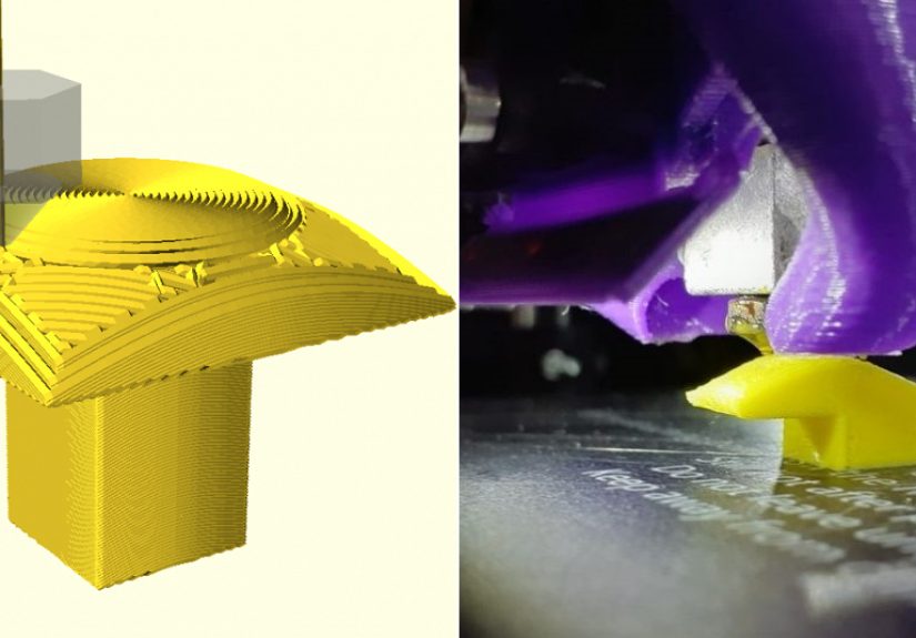
Specific Example: Printing a Small Supportless Shelf
Imagine a small test part shaped like a vertical wall with a horizontal shelf projecting outward. In a standard slicer, the shelf underside triggers supports because the first shelf layers have little or no material underneath. With non-planar or conic slicing, the shelf can be approached as a progressive outward build. Instead of printing a sudden flat ledge, the toolpath creates angled layers that gradually extend from the wall.
The result is not always identical to a traditionally supported overhang. The underside may show directional texture from the non-planar paths. Dimensional accuracy may require compensation. Edges may need tuning. But if the goal is a clean supportless ledge with less scarring and less waste, the approach can be surprisingly effective.
A practical workflow might look like this: design the part with clearance around the overhang, preview the collision envelope, choose a non-planar or conic path strategy for the overhang region, keep the rest of the part planar, slow down the overhang toolpaths, maximize part cooling for PLA, and print a small test before committing to the final model. The test print is not optional. It is the difference between engineering and donating filament to the blob gods.
Design Tips for 90° Overhangs With Non-Planar Slicing
1. Design for Gradual Growth
A sharp unsupported ledge is harder than a ledge that grows from a curved or angled transition. If the part allows it, add a small radius, chamfer, or progressive underside. This gives the slicer more room to generate stable paths.
2. Keep Toolhead Clearance in Mind
The nozzle tip is not the whole printhead. Before attempting non-planar printing, consider the heater block, fan duct, probe, and silicone sock. A long nozzle or compact toolhead can increase the safe non-planar angle.
3. Use Hybrid Slicing When Possible
There is no trophy for making the entire model non-planar if only one region needs it. Use planar slicing for simple sections and non-planar paths for the overhang, curved top surface, or cosmetic region.
4. Tune Cooling Before Blaming the Slicer
Poor cooling can ruin even a clever toolpath. For PLA, strong and well-directed part cooling is often the difference between a clean overhang and a droopy plastic mustache.
5. Start Small
Test coupons are your friend. A small wall-and-shelf model can reveal whether your printer, filament, and G-code are ready before you risk a complex part.
Common Problems and How to Think About Them
Curling edges: Curling often means the plastic is staying hot too long, the overhang speed is too high, or the extrusion is not bonding as expected. Increase cooling, slow the path, or reduce temperature carefully.
Toolhead collision: This is a geometry and clearance issue, not a “try again harder” issue. Check the preview, reduce the non-planar height, modify the part, or change hardware clearance.
Rough underside texture: A supportless underside may still show path lines. Adjust path direction, layer spacing, cooling, and extrusion width. Also ask whether the underside must be perfect or merely better than a support scar.
Weak bonding: If the non-planar layers do not fuse well, temperature may be too low, speed too high, or the toolpath overlap insufficient. Strength tests matter for functional parts.
Firmware surprises: Some printers handle simultaneous XYZ motion beautifully. Others may produce tiny pauses, uneven motion, or artifacts. Non-planar printing exposes motion-control behavior that ordinary flat layers may hide.
The Future of Non-Planar Slicing
Non-planar slicing is moving from fascinating experiment toward practical workflow, but it still has obstacles. The next big improvements will likely come from better slicer interfaces, automated collision checking, printer-specific toolhead models, improved preview tools, and smarter hybrid slicing. Once users can select “non-planar overhang region” as easily as they now paint supports, adoption will grow quickly.
Multi-axis desktop printing may also become more accessible. A 4-axis or 5-axis printer can orient the nozzle or part in ways that make supportless printing more natural. That said, software remains the hard part. Hardware can spin, tilt, and pose dramatically for the camera, but without reliable toolpath planning, it is just a robot doing interpretive dance.
For now, the most realistic path is hybrid: normal FDM printing for most geometry, non-planar toolpaths for selected surfaces and overhangs, and careful design choices that make the print physically possible. That approach is less flashy than “supports are dead,” but it is far more useful.
Experience Notes: What It Feels Like to Work With 90° Non-Planar Overhangs
The first experience most makers have with non-planar overhang printing is not pure triumph. It is curiosity mixed with suspicion. You slice a model, rotate the preview, and realize the nozzle is no longer moving in the obedient flat layers you are used to. The path rises, dips, and leans. It looks smart. It also looks like something that might detach your fan duct if you forgot one clearance check. This is where the learning begins.
One practical lesson is that the model matters as much as the slicer. A normal overhang test designed for planar printing may not show the true value of non-planar slicing. Better tests include a vertical wall with a controlled ledge, a curved duct outlet, or a small bracket where the underside is visible. When the geometry gives the slicer room to create gradual toolpaths, the results can be impressive. When the model demands an abrupt horizontal jump, the slicer has fewer tricks available.
Another experience is that print cooling becomes very personal. Two printers with the same nozzle size, same filament, and same G-code can produce different overhang quality because the fan duct points air differently. A strong duct that cools both sides of the extrusion can make a difficult overhang look controlled. Weak or uneven cooling can create curling, especially near corners where heat accumulates. PLA is usually friendlier for experiments because it stiffens quickly. PETG may need more patience because it likes to stay glossy, sticky, and emotionally attached to the nozzle.
Speed is the next big lesson. Fast printers are exciting, but non-planar overhangs reward calm motion. Slowing down the overhang region gives the bead time to land, bond, and cool. The goal is not to win a race; the goal is to convince a strand of hot plastic to become architecture. Lower acceleration can also help because sudden direction changes can exaggerate ringing or disturb delicate unsupported edges.
G-code preview becomes mandatory. In normal printing, many users trust the slicer and press start. With non-planar overhangs, previewing is part of the craft. Watch the Z movement. Look for travel moves that pass near printed walls. Check whether the toolhead would cross a tall feature. Make sure the non-planar region starts and ends cleanly. A beautiful toolpath that collides with the part is not advanced manufacturing; it is slapstick with stepper motors.
Dimensional accuracy also deserves attention. A supportless 90° overhang may print cleanly but still need compensation. Edges can be slightly rounded. The underside may have a directional grain. Corners may need fillets or extra cooling time. For decorative parts, this texture can look intentional and even attractive. For functional parts, test fit matters. A supportless bracket that looks amazing but misses a critical dimension is still a failed bracket wearing a nice suit.
The biggest mindset shift is accepting that non-planar slicing is not merely a setting. It is a design strategy. The best results come when CAD, slicing, hardware, filament, and printer tuning all cooperate. Once that clicks, 90° overhangs stop feeling impossible and start feeling like a solvable geometry problem. The process is not always plug-and-play, but it is deeply satisfying. Few things in desktop 3D printing feel better than watching a printer create a clean ledge where you expected a messy support forest.
Conclusion: Non-Planar Slicing Does Not Break the RulesIt Rewrites the Path
3D printing 90° overhangs with non-planar slicing is one of the clearest examples of how toolpath strategy can change what an FDM printer can do. Traditional planar slicing stacks flat layers and struggles when geometry becomes horizontal. Non-planar slicing gives the printer a more flexible way to build, allowing curved, inclined, or conic paths that can reduce support needs and improve surface quality.
This does not mean supports are obsolete. It means they are no longer the only answer. For the right model, printer, material, and slicer workflow, non-planar slicing can produce supportless overhangs that would normally be difficult or ugly with standard methods. The tradeoff is complexity: collision checking, hardware clearance, cooling, speed, flow, and design intent all matter.
The exciting part is that this field is still young. As slicers become smarter and printers become more aware of their own toolhead geometry, non-planar overhang printing may become a normal option rather than a research-flavored adventure. Until then, it remains one of the most rewarding experiments in FDM printing: a place where geometry, software, and molten plastic team up to make a 90° overhang behave itself for once.