Table of Contents >> Show >> Hide
- What Makes Digital Calipers Hackable?
- How the Data Stream Works
- Hardware Needed for a Caliper Automation Hack
- Software: Decoding the Measurement
- Automated Measurements: What Can You Actually Do?
- The Truth About “Sorta-Micron Accuracy”
- Improving Repeatability the Smart Way
- Commercial SPC vs. DIY Caliper Hacking
- Common Mistakes to Avoid
- Experience Notes: What This Hack Feels Like in the Real World
- Conclusion
Digital calipers are the quiet overachievers of the workshop. They sit in a drawer, survive sawdust, coolant mist, questionable coffee spills, and the occasional dramatic fall from a workbench, then calmly tell you whether your part is 12.04 mm or “try again, champ.” But hidden behind many inexpensive digital calipers is something more interesting than a bright LCD: a tiny data output port that can be hacked for automated measurements.
That is where the fun begins. By tapping into the caliper’s clock and data signals, makers can turn a simple handheld measuring tool into a sensor for logging dimensions, monitoring machine movement, sorting parts, or studying repeatability. The phrase “sorta-micron accuracy” deserves a raised eyebrow, of course. A budget caliper may output tiny digital increments, but that does not magically transform it into a laboratory-grade micrometer. Still, with careful electronics, smart filtering, and realistic expectations, hacking digital calipers can unlock surprisingly useful automated measurement systems.
What Makes Digital Calipers Hackable?
Many digital calipers, especially inexpensive imported models and higher-end SPC-ready tools, include a small covered port on the slider body. Under that cover, you may find four contacts: power, ground, clock, and data. The caliper’s internal electronics continuously measure the position of the slider along the scale and send that reading as a serial data stream.
In practical terms, the caliper is already doing the hard part: sensing position. The hacker’s job is to listen politely instead of poking around like a raccoon in a toolbox. A microcontroller or single-board computer can read the signal, decode the bits, convert the result into millimeters or inches, and send it to a computer, spreadsheet, database, CNC controller, or custom application.
The Common Four-Pin Caliper Output
While caliper protocols vary by brand and model, many low-cost digital calipers expose a simple synchronous serial interface. The clock line tells the receiving device when to sample the data line. The data line carries the measurement value, often least-significant bit first. Some calipers send one 24-bit word. Others send two 24-bit words, such as an absolute position and a relative position based on the last zero setting.
The tricky part is voltage. Because many digital calipers run from a 1.5-volt button cell, their logic signals may also be around 1.5 volts or lower. That is not friendly to a typical 5-volt Arduino input, and it may not reliably register as a high signal on a Raspberry Pi either. That is why level shifting is a major part of most digital caliper hacks.
How the Data Stream Works
A digital caliper output is not usually USB, UART, or I2C. It is more like a private little conversation between the caliper and whatever factory accessory cable was supposed to read it. The protocol can feel mysterious until you look at it with a logic analyzer. Then it becomes slightly less mysterious and more like a tiny Morse-code accountant.
On many calipers, the data stream arrives in packets. A long clock pause may mark the beginning of a new reading. Each following clock pulse corresponds to a bit. The receiving circuit samples the data line on a specific clock edge, often the falling edge. After collecting enough bits, the software assembles the value, checks the sign bit, applies scaling, and displays or logs the result.
Example: 24-Bit Readings
In one common pattern, the caliper sends 24 bits per packet. The first bit may be a start or dummy bit, followed by measurement bits and a sign bit. In millimeter mode, the decoded number may represent hundredths of a millimeter, meaning a displayed reading of 7.01 mm might appear as the integer 701 before formatting. Other models use inch-based internal units, such as counts per inch, and require a different conversion formula.
This is why the first rule of hacking digital calipers is: do not assume your caliper uses the same protocol as someone else’s caliper. Two tools that look nearly identical on the outside may speak slightly different electronic dialects. The second rule is: never underestimate how much confusion can be caused by a missing ground connection. It is the workshop equivalent of forgetting to plug in the toaster and blaming the bread.
Hardware Needed for a Caliper Automation Hack
You can build a basic automated digital caliper reader with a modest set of parts. The exact design depends on whether you are using an Arduino, ESP32, Raspberry Pi, RP2040 board, or another microcontroller. The general ingredients are similar.
Basic Parts List
- Digital caliper with data output contacts
- Microcontroller or single-board computer
- Level-shifting circuit for clock and data lines
- Stable power source for the caliper
- Wires, connector, or soldered leads
- Optional logic analyzer for decoding and debugging
- Optional capacitors or filtering components for noise control
- Software to decode, filter, display, and log readings
The connector is often the most annoying part. Some calipers have a tiny edge connector that accepts a commercial data cable. Others require improvised spring contacts, a 3D-printed plug, or, for the brave and mildly reckless, soldered wires secured with hot glue. Soldering directly to the pads works, but it turns a pocket tool into a bench fixture. Choose your path based on whether you want a reusable caliper or a permanent measurement sensor.
Level Shifting Without Tears
The caliper’s low-voltage clock and data signals must be translated into logic levels your controller can read. A simple transistor circuit can work. A Schmitt-trigger buffer can work better because it cleans up slow or noisy edges. Dedicated level shifter ICs are also a clean option. Some Raspberry Pi hacks use resistor networks to bias the caliper signal near the Pi’s input threshold, but that approach requires caution because it can be sensitive to noise and component tolerances.
For a durable build, use a proper level shifter or comparator-style input stage. Add strain relief to wires. Keep leads short. Put the electronics in a small enclosure. The difference between a “neat measuring instrument” and a “desk spaghetti monster” is usually one afternoon with heat shrink and a project box.
Software: Decoding the Measurement
Once the hardware produces readable logic levels, the software can capture the data. The usual approach is interrupt-driven: wait for a clock edge, read the data pin, shift the bit into a buffer, and count until a full packet arrives. A timer can identify the long pause between packets and reset the bit counter.
Typical Decoding Workflow
- Detect the start of a new packet by watching the clock timing.
- Sample the data line on the correct clock edge.
- Store each incoming bit in order.
- Convert the bit field into a signed integer.
- Apply the proper scaling factor for millimeters or inches.
- Reject malformed packets or impossible jumps.
- Average, filter, or smooth the result if needed.
- Send the final reading to USB serial, Wi-Fi, Bluetooth, CSV, Excel, or a database.
The most important software habit is skepticism. Caliper data can glitch. The clock can jitter. A packet may be incomplete. A button press can interfere with the data line on some models. If your code accepts every number as sacred truth, it will eventually log a part as being 8,388,608 mm wide, which is less “precision engineering” and more “measuring a continent.”
Automated Measurements: What Can You Actually Do?
Automating digital calipers is useful whenever manual reading becomes repetitive, slow, or error-prone. This does not mean the caliper suddenly becomes a coordinate measuring machine. It means the tool becomes a low-cost sensor for a specific job.
1. Logging Repeated Measurements
Suppose you are measuring 200 printed parts, turned spacers, or 3D-printed test coupons. Manually reading the display and typing each value into a spreadsheet is boring, and boredom is where typos breed. With a caliper interface, you can press a button or trigger a reading automatically and send the value straight to a CSV file. The result is faster data collection and fewer “was that 14.62 or 14.26?” moments.
2. Sorting Parts by Size
A hacked caliper can become part of a sorting jig. Place a part between the jaws, capture the dimension, and classify it as pass, fail, oversize, undersize, or “mystery object from the bottom of the drawer.” Add LEDs, a small display, or a buzzer, and you have a basic quality-control station.
3. Monitoring Machine Movement
For short travel distances, a digital caliper can act as a linear position sensor. Makers have used calipers to monitor small lathes, router axes, drill press depth, and test rigs. This is especially appealing when the alternative is buying a dedicated digital readout system. However, calipers are not built for heavy side loads, vibration, coolant flooding, or chips packed into the beam. Use them gently and shield them well.
4. Capturing Experimental Data
Digital calipers can also help with experiments: material expansion, fixture deflection, spring compression, wear testing, or small displacement tracking. If the setup is stable and the measurement force is controlled, automated logging can reveal trends that are difficult to catch by eye.
The Truth About “Sorta-Micron Accuracy”
Here is the important reality check: resolution is not accuracy. A digital caliper may output internal counts that appear smaller than 0.01 mm. Some decoded streams may even suggest micron-ish increments. But the jaws, slider, scale, electronics, operator force, alignment, temperature, and calibration all affect the actual measurement.
A typical digital caliper may display 0.01 mm or 0.0005 inch resolution. Many quality calipers are rated around plus or minus 0.02 mm to 0.03 mm over common ranges, while many shop-grade calipers are commonly treated as roughly plus or minus 0.001 inch tools when properly used and calibrated. That is excellent for a handheld instrument, but it is not the same as true micron-level accuracy.
Why the Extra Digits Can Mislead You
When decoded from the raw data stream, the caliper may appear to provide more bits than the display shows. Tempting? Absolutely. Useful? Sometimes. Dangerous? Also yes. Extra bits may jitter between values because the internal sensing system, mechanical slider, and signal processing were never intended to guarantee reliable micron measurements.
Averaging can reduce random noise, but it cannot remove jaw flex, dirt on the beam, cosine error from a tilted part, thermal expansion, or inconsistent thumb pressure. If you squeeze the jaws like you are trying to interrogate the workpiece, your reading will change. The caliper is not lying; your hand is just louder than the least significant bit.
Improving Repeatability the Smart Way
If you want better automated measurements, focus on repeatability first. Repeatability means the system gives the same reading when the same part is measured under the same conditions. Without repeatability, accuracy is just a motivational poster.
Use a Fixed Fixture
Mount the caliper rigidly so the part contacts the jaws the same way every time. Avoid side loading the slider. If measuring thickness, use a stop so the part enters at the same depth. If measuring travel, align the caliper beam with the movement axis to avoid cosine error.
Control Measuring Force
Human measuring force is a major source of variation. A spring-loaded fixture, light gravity feed, or constant-force mechanism can make readings more consistent. Even a simple stop that prevents over-squeezing can help.
Calibrate Near the Working Range
If your measurement target is around 25 mm, check the caliper against a known standard near 25 mm. Zeroing the jaws is helpful, but it does not prove the entire range is accurate. Gauge blocks or certified standards are ideal for serious work.
Filter With Purpose
Software filtering should match the application. A moving average can smooth jitter in a slow experiment. A median filter can reject occasional spikes. Packet validation can discard impossible data. But too much filtering creates lag, which is bad for live position feedback. Do not polish the data until it becomes fiction.
Commercial SPC vs. DIY Caliper Hacking
Professional digital calipers often support SPC, or statistical process control, through wired or wireless data output. In a shop environment, SPC systems collect measurements electronically, reduce manual entry errors, and help operators track process variation. Commercial systems may send readings directly into Excel, quality-control software, or a manufacturing database.
DIY caliper hacking is the budget cousin of that workflow. It may not have the rugged connectors, certified cables, or polished software of a commercial system, but it offers flexibility. You can log every reading, trigger captures from a foot pedal, stream data over Wi-Fi, build a Python dashboard, or connect the caliper to a sorting machine. For makers, labs, and small shops, that flexibility is often the whole point.
Common Mistakes to Avoid
The first mistake is wiring the caliper directly to a controller without understanding voltage levels. The second is assuming every caliper uses the same packet format. The third is believing that more digits mean more truth. The fourth is building a beautiful data logger and forgetting the mechanical fixture, which is like putting racing tires on a shopping cart.
Also watch out for auto-off behavior. Some calipers turn off the display but continue drawing power. Others lose reference or stop sending data after inactivity. If the caliper will be permanently installed in a machine, consider external power, but do it carefully. A stable supply can eliminate dead batteries, but a careless supply can eliminate the caliper.
Experience Notes: What This Hack Feels Like in the Real World
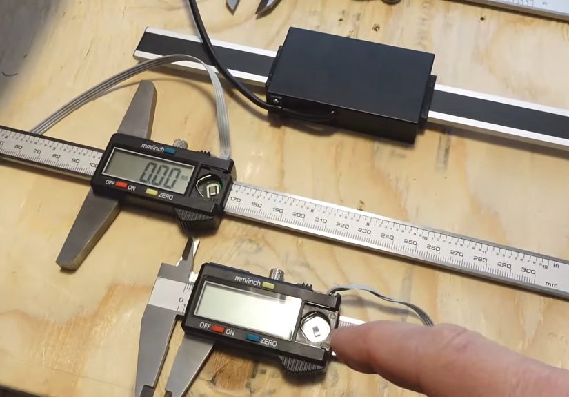
The first time you open the little data-port cover on a digital caliper, it feels like discovering a secret level in a video game. There are the tiny contacts, sitting there like they know something. You connect a ground clip, poke the pins with a logic analyzer, and suddenly the quiet caliper is chattering away in pulses. It is a satisfying moment because the tool stops being just a display and becomes a sensor.
In practice, the hardest part is rarely the code. The code is fussy, but manageable. The real headaches come from physical connections, noise, and inconsistent mechanics. A wire that works perfectly while the caliper sits on the bench may fail the moment you mount it to a moving jig. A connector that looks clever in CAD may have contacts that barely touch. A signal that looks clean at 2 p.m. may turn into digital confetti when a motor, spindle, or power supply starts nearby.
A useful habit is to build the project in layers. First, read the raw clock and data with a logic analyzer. Second, confirm the voltage levels. Third, write a tiny decoder that prints raw packets. Fourth, move the jaws slowly and verify that the decoded value increases and decreases in the expected direction. Fifth, add units and sign handling. Only after that should you add smoothing, logging, buttons, displays, or wireless features.
For automated sorting, the best results come from treating the caliper as part of a fixture, not as a handheld tool. The jaws should meet the part in the same place every time. The part should sit against a stop. The measurement force should be consistent. A cheap caliper in a smart fixture can outperform a nicer caliper used casually by tired hands at the end of a long day.
For machine-position monitoring, protect the caliper from abuse. Chips, dust, vibration, and side load are not its natural habitat. Add covers. Keep the beam clean. Avoid using the caliper as a structural member. Let it measure motion, not survive a wrestling match with the machine frame.
The most charming part of the whole project is also the most humbling: the data will teach you metrology manners. You will see readings drift when the tool warms in your hand. You will see noise when wires are too long. You will see repeatability improve when the fixture gets better. And you will learn that “sorta-micron accuracy” is best understood as a playful goal, not a legal contract. The hack is valuable because it turns measurement into data, and data into insight. Just keep a sense of humor nearby, preferably next to the hot glue gun.
Conclusion
Hacking digital calipers for automated measurements is one of those projects that beautifully bridges electronics, machining, coding, and practical metrology. A simple caliper can become a data logger, a sorting station, a displacement sensor, or a quality-control helper. The core idea is straightforward: read the caliper’s clock and data lines, level-shift the signals, decode the packet, filter the noise, and log the result.
The key is to stay honest about the tool. Digital calipers are wonderfully useful, but they are not magic micron machines. Extra data bits can offer finer apparent resolution, yet real accuracy depends on calibration, measuring force, alignment, temperature, mechanical stability, and common sense. Use the hack for automation, trend tracking, repeatability studies, and clever workshop tools. For certified micron-level measurement, reach for the proper instrument and calibration process.
Note: This article is intended for educational and editorial use. For safety-critical, regulated, or high-tolerance manufacturing work, verify measurements with calibrated tools, proper standards, and documented uncertainty procedures.