
Table of Contents >> Show >> Hide
- Why Build Pong With Discrete Components?
- The Historical Spark: Pong Before Code Took Over
- What “Discrete Components” Means in a Pong Build
- The Core Idea: Turn Time Into Position
- Choosing a Video Output: Composite or VGA?
- Generating Sync Signals
- Drawing the Paddles
- Creating the Ball
- Collision Detection: When Logic Becomes Gameplay
- Scoring Without a CPU
- Adding Sound Effects
- Power, Grounding, and Signal Discipline
- Useful Building Blocks for a Discrete Pong Circuit
- Testing Strategy: Do Not Build Everything at Once
- Common Problems and Practical Fixes
- Modern Lessons From an Old Game
- Hands-On Experience: What Building Discrete Pong Actually Feels Like
- Conclusion
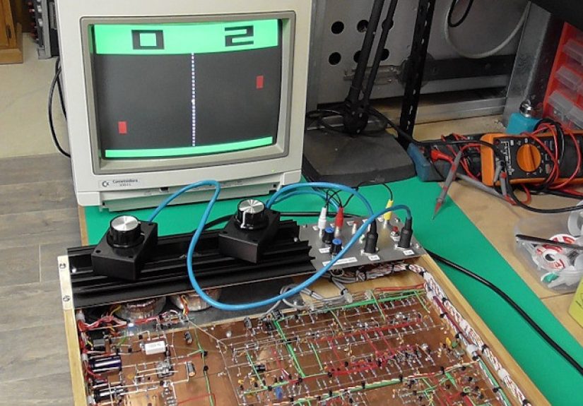
Building Video Pong with discrete components is the electronics equivalent of cooking a full dinner without a microwave, food processor, or even a recipe app. It is slower, messier, and occasionally makes you question your life choices. But when a white square bounces across a screen because of counters, gates, flip-flops, resistors, capacitors, and your own stubbornness, the result feels almost magical.
Today, Pong can be recreated in a few lines of code on an Arduino, Raspberry Pi, FPGA board, or web browser. That is convenient, but it also hides the wild engineering trick behind the original idea: early video games did not need software to be interactive. Atari’s original Pong was famously built before microprocessors became the obvious choice for arcade games. Its logic was hardwired. The “program” was the circuit itself.
This article explores how a discrete-component Video Pong project works, why it is still a brilliant learning challenge, and what builders should expect when turning simple logic into moving graphics. We will look at video timing, paddle control, ball movement, collision detection, scoring, sound, and the deeply humbling art of debugging a circuit that refuses to blink where it should.
Why Build Pong With Discrete Components?
There are easier ways to build Pong. That is not the point. The point is to understand how video can be generated from raw timing signals and how game behavior can emerge from hardware alone. A discrete Pong build turns abstract electronics into something you can see, play, and complain about when Player Two wins by exploiting your questionable paddle design.
For students, hobbyists, retro-computing fans, and hardware hackers, the project is a perfect bridge between digital logic and visual output. You do not merely learn that a counter increments. You watch that counter become horizontal screen position. You do not simply wire a comparator. You use it to decide whether the ball has touched a paddle. Suddenly, Boolean logic stops being a truth table and starts being a very opinionated referee.
The Historical Spark: Pong Before Code Took Over
Pong became one of the defining arcade games of the early 1970s. Designed by Allan Alcorn at Atari, it showed that a simple screen, two paddles, a moving dot, and a score could pull people into coin-operated video play. The brilliance was not only the gameplay but the implementation. Early arcade hardware relied on dedicated circuits, not general-purpose processors running software.
That design philosophy matters. Instead of writing instructions like “move ball one pixel right,” the circuit created conditions. A horizontal counter advanced across the scan line. A vertical counter advanced down the frame. Logic gates compared those positions against stored or generated coordinates. When the counter position matched the ball’s position, the video output went bright. When the ball overlapped a paddle region, the direction changed. The game was not executed line by line. It existed continuously as electricity moving through logic.
That is why building Video Pong with discrete components remains such a satisfying project. It recreates the mindset of early arcade engineering: build the world first, then let the signals play inside it.
What “Discrete Components” Means in a Pong Build
In modern hobby language, “discrete components” can mean slightly different things. Strictly speaking, it refers to individual electronic parts such as transistors, diodes, resistors, and capacitors. In many retro digital projects, the phrase is also used more broadly to mean building without a microcontroller or CPU, using small-scale logic integrated circuits such as 7400-series NAND gates, counters, flip-flops, multiplexers, comparators, and timers.
A practical Video Pong build usually combines both worlds. You may use TTL or CMOS logic chips for counters and gates, analog parts for video levels, potentiometers for paddle control, and perhaps 555 timers or simple oscillators for sound. The important rule is that the gameplay is not software-driven. There is no loop, no sprite engine, no graphics library, and no secret Python script hiding behind the curtain. The circuit is the engine.
The Core Idea: Turn Time Into Position
Every video Pong circuit begins with a beautiful trick: screen position is just time. A display draws one line after another. If your circuit knows where the beam, pixel clock, or scan position is at any moment, it can decide whether to output black or white.
For a CRT-style or VGA-inspired design, you create two main timing systems: horizontal timing and vertical timing. Horizontal timing tracks position from left to right across a line. Vertical timing tracks which line is currently being drawn from top to bottom. Together, these two values form an X and Y coordinate system.
Once you have X and Y coordinates, Pong becomes a collection of yes-or-no questions:
- Is the current X position inside the left paddle?
- Is the current Y position within the paddle height?
- Is the current X and Y position inside the ball square?
- Is this pixel part of the center line?
- Should the score be displayed here?
If the answer is yes, the circuit sends a bright video signal. If the answer is no, it sends black. That is the whole visual universe of classic Pong: simple timing, simple shapes, and brutally honest logic.
Choosing a Video Output: Composite or VGA?
One of the first design choices is whether to generate composite video or VGA. Both are possible, but they feel different in practice.
Composite Video
Composite video feels historically appropriate. It can work with old televisions, small security monitors, and certain capture devices. However, it requires careful sync generation and correct voltage levels. Composite video combines image brightness and synchronization into one signal, so small mistakes can produce rolling screens, unstable images, or the legendary “I swear it worked five minutes ago” waveform.
VGA
VGA is often friendlier for modern builders. A common beginner target is 640×480 at 60 Hz, which uses separate horizontal and vertical sync signals plus analog color channels. Even if the project only outputs monochrome graphics, VGA gives you clean timing boundaries and easier testing with many monitors. The pixel clock and timing requirements still matter, but the separation of sync and video makes debugging less mysterious.
For a first discrete Pong build, VGA is usually the better learning path. For a historically flavored challenge, composite video is wonderfully authentic and occasionally spicy enough to make an oscilloscope feel like a therapist.
Generating Sync Signals
Video displays need synchronization signals so they know when a line or frame begins. A Pong circuit must produce these signals reliably. This is usually done with an oscillator feeding binary counters. The horizontal counter resets at the end of each line. The vertical counter increments after each completed line and resets at the end of the frame.
Logic gates decode certain counter ranges to create blanking intervals and sync pulses. During active video, the circuit draws paddles, ball, center line, and score. During blanking, it suppresses visible output while the display returns to the next line or frame.
This is where builders discover that video timing is not forgiving. A counter reset one clock too early can shift the picture. A sync pulse too wide can confuse a monitor. A missing ground connection can turn your elegant game into a modern art installation called “Rectangle Having a Bad Day.”
Drawing the Paddles
The paddles are usually vertical rectangles. To draw one, the circuit checks whether the current X coordinate equals the paddle’s fixed horizontal location and whether the current Y coordinate falls within the paddle’s vertical range.
The simplest paddle control uses a potentiometer. The analog voltage from the potentiometer can be converted into a timing threshold or compared against a ramp signal. In a more digital design, an up/down counter stores paddle position. Pressing up or down changes the counter value, and comparators decide whether the current scan line overlaps the paddle.
Each method has personality. Potentiometers feel smooth and arcade-like. Up/down buttons are easier to keep fully digital. A hybrid design can use analog input for feel and digital logic for display. The key is to produce a stable paddle position that can be compared with vertical scan timing.
Creating the Ball
The ball is just a small block of active video. The circuit stores or generates a ball X position and a ball Y position. During each frame, comparators check whether the current scan coordinate lies within that small rectangular region. If yes, the video output turns on.
Movement requires changing the ball position over time. In a software game, you would update variables. In hardware, you use counters, flip-flops, direction bits, and clock pulses. One flip-flop may represent horizontal direction: left or right. Another represents vertical direction: up or down. At a slower game clock, the ball X counter increments or decrements, and the ball Y counter does the same.
The ball should not update at the pixel clock rate, or it will teleport across the screen like it has somewhere better to be. Instead, the circuit updates ball position once per frame or after a divided-down timing pulse. This creates visible motion at a playable speed.
Collision Detection: When Logic Becomes Gameplay
Collision detection is the part of the project where Pong stops being a video test pattern and becomes a game. The circuit must detect when the ball overlaps a paddle, the top or bottom boundary, or a scoring zone beyond the left or right edge.
Wall collisions are relatively simple. If the ball Y position reaches the top boundary, flip the vertical direction bit. If it reaches the bottom boundary, flip it again. Paddle collisions require checking both X and Y overlap. The ball must be near the paddle’s horizontal position, and its vertical range must intersect the paddle’s vertical range.
A more advanced build can imitate the original Pong trick of changing the return angle depending on where the ball strikes the paddle. Hit near the center, and the ball travels more horizontally. Hit near the top or bottom, and the ball takes a sharper vertical path. In discrete logic, this can be approximated by altering the vertical update rate, changing direction rules, or using a few paddle “zones” decoded by comparators.
This one feature transforms the game. Without angle variation, Pong can become predictable. With it, the circuit suddenly feels clever, as if a handful of chips developed competitive instincts.
Scoring Without a CPU
Scoring is another fun challenge. When the ball passes beyond the left edge, the right player earns a point. When it passes beyond the right edge, the left player scores. Each player can have a counter storing the score. The display can show digits using seven-segment-style logic, simple block numerals, or a row of marks.
The easiest route is to display score bars or small tally blocks. A more ambitious route uses binary-coded decimal counters and display decoding logic. If the video output must draw numeric digits on the same screen, the project needs character-shape logic. This can be done with diode matrices, ROM-like lookup circuits, or combinational gate networks. It is possible, but it adds complexity quickly.
For a first build, simple score indicators are perfectly respectable. Nobody loses arcade credibility because the score is shown as five glowing blocks instead of a polished digital font. The ball is moving. The paddles work. Take the win.
Adding Sound Effects
Classic Pong sound is charming because it is so basic. A short beep for paddle hits, another tone for wall bounces, and perhaps a lower or longer tone for scoring are enough. Sound can be produced with a 555 timer, a gated oscillator, or logic-derived pulses filtered into a small amplifier.
The events that trigger sound already exist in the circuit: paddle collision, wall collision, and score detection. These pulses can enable different oscillators or alter one oscillator’s frequency. The result is not orchestral. It is barely musical. But it is deeply satisfying because the sound comes directly from game events in hardware.
Power, Grounding, and Signal Discipline
Discrete digital video projects are sensitive to layout. Breadboards are convenient, but they introduce capacitance, resistance, and accidental antennas that become more annoying at video frequencies. A small test circuit may behave on a breadboard, while a full Pong system becomes unstable once dozens of jumpers enter the party.
Good power distribution matters. Each logic IC should have a decoupling capacitor close to its power pins. Ground lines should be short and solid. Clock signals should be routed carefully. Inputs should not be left floating. Video output resistors should be chosen to create safe, expected signal levels for the display.
In other words, the project teaches digital electronics and manners. The circuit will punish sloppy wiring with flicker, ghosting, jitter, and random glitches. It is not being rude. It is being educational.
Useful Building Blocks for a Discrete Pong Circuit
A complete design can vary, but many builds use the same families of parts and functional blocks:
- Oscillator: Generates the master clock for video timing.
- Binary counters: Track horizontal and vertical scan positions.
- Logic gates: Decode timing ranges and combine shape signals.
- Comparators: Detect overlap between scan position and objects.
- Flip-flops: Store ball direction, game states, and collision events.
- Multiplexers: Select between video elements or control paths.
- Potentiometers or buttons: Provide player input.
- Resistors and capacitors: Shape analog video levels and stabilize power.
- Audio oscillator: Produces simple beeps for collisions and scoring.
The magic comes from connecting these blocks so they behave like a tiny physical universe. The ball does not “know” it is bouncing. A direction bit flips because a comparator and a gate agreed that the ball touched something. That is the poetry of hardware, assuming poetry occasionally requires a logic probe.
Testing Strategy: Do Not Build Everything at Once
The fastest way to fail is to wire the entire game before testing anything. A better approach is modular.
Step 1: Prove the Video Timing
Start by generating stable sync and a basic test pattern. Draw vertical bars, horizontal bars, or a border. If the monitor locks onto the signal and the pattern is stable, you have a foundation.
Step 2: Draw Static Objects
Add fixed paddles and a center line. These objects prove that your coordinate decoding works.
Step 3: Add Player Control
Make one paddle move, then the other. Confirm that movement is smooth and stays within boundaries.
Step 4: Add the Ball
Draw a static ball first. Then make it move horizontally. Then vertically. Then combine both directions.
Step 5: Add Collisions and Scoring
Once motion is reliable, add collision detection. Finally, add scoring and sound. By this stage, you are no longer building a circuit. You are negotiating with a tiny arcade machine.
Common Problems and Practical Fixes
If the screen rolls vertically, check vertical sync timing and blanking. If the image tears or shifts sideways, inspect horizontal sync. If objects appear in the wrong place, verify counter reset points and comparator wiring. If the ball disappears, check whether its X and Y overlap signals are being combined correctly. If paddles jitter, stabilize input signals and debounce buttons if needed.
Another common issue is accidental multiple triggering. Collision detection may fire for several frames or several clock cycles, causing the ball to flip direction repeatedly and appear stuck inside a paddle. The fix is to latch collision events carefully or ensure that the ball moves away after a hit before another collision can register.
Debugging is easier with an oscilloscope or logic analyzer, but even LEDs can help at low-speed points. Add temporary indicators for frame pulses, direction bits, score triggers, and collision events. A glowing LED can save an afternoon of dramatic sighing.
Modern Lessons From an Old Game
Building Video Pong with discrete components teaches concepts that still matter in modern engineering. Video timing relates to display systems. State machines relate to processors, communication protocols, and control systems. Signal integrity matters in everything from hobby boards to professional hardware. Even game design lessons appear: simple mechanics can be compelling when feedback is immediate and rules are clear.
It also changes how you think about software. Programmers often imagine hardware as a platform that obediently runs code. A discrete Pong build reminds you that computation can be physical, parallel, and continuous. Every gate acts at once. Every signal has timing. Every shortcut has consequences.
Hands-On Experience: What Building Discrete Pong Actually Feels Like
The first emotional stage of building discrete Pong is confidence. The circuit diagram looks logical. The counters make sense. The paddle is just a rectangle. The ball is just another rectangle. You tell yourself, “How hard can this be?” This sentence is widely recognized by electronics projects as a formal invitation to misbehave.
The second stage is respect. Video timing has no interest in your optimism. A display expects sync pulses at the right time, blanking in the right region, and video levels that make electrical sense. When you finally get a stable rectangle on the screen, it feels like discovering fire, except the fire is a white block and it took three evenings to stop drifting sideways.
One of the best experiences is seeing the project become playable one layer at a time. A blank screen becomes a border. A border becomes paddles. The paddles move. Then a square appears. Then the square moves. Then it bounces. Each step feels small on paper, but on the bench it feels enormous. You are not importing a game engine; you are building every rule from voltage and timing.
The most humbling moments usually involve assumptions. You assume a signal is clean, but it has noise. You assume a button press is a single event, but it bounces like popcorn. You assume a collision pulse is brief, but it lasts long enough to reverse the ball twice. You assume all logic chips agree on what “high” means, then discover that mixing families without care can create strange behavior. The project teaches patience because the circuit will not accept motivational speeches as valid input.
Another memorable experience is the shift from “debugging electronics” to “debugging game feel.” Once the game works, you start noticing whether the ball is too slow, too fast, too predictable, or too difficult. A purely technical build becomes a design exercise. Should the paddle be taller? Should the ball speed increase after each hit? Should the top and bottom walls be closer to the active area? These questions sound like game development, but the answers require rewiring, changing counters, adjusting dividers, or adding logic. It makes you appreciate how much design effort early arcade engineers squeezed out of limited hardware.
The project also rewards tidy construction. A neat layout is not just pretty; it is survival. Labeling signals, keeping clock lines short, grouping related chips, and using consistent power rails make the difference between progress and chaos. Many builders start on a solderless breadboard, then migrate stable modules to perfboard or a printed circuit board. That migration can feel like moving from a tent into a house with actual walls.
Perhaps the best part is showing the finished game to someone who has only seen software-based games. When you explain that there is no CPU and no code controlling the action, the reaction is usually a confused smile followed by a closer look at the board. The visible complexity makes the simple gameplay more impressive. Pong is no longer “just two paddles and a dot.” It becomes a tiny museum of digital logic, playable with your own hands.
In the end, the experience is part engineering lesson, part historical reenactment, and part puzzle box. You gain practical knowledge of counters, gates, timing, video signals, and debugging. You also gain a new appreciation for early game hardware, where creativity had to fit inside real electrical limits. And when that first clean bounce appears on the screen, the little beep sounds less like a beep and more like applause.
Conclusion
Building Video Pong with discrete components is not the easiest way to make a game, but it may be one of the most rewarding. It strips video game design down to timing, logic, voltage, and feedback. The project reveals how early arcade engineers turned simple circuits into interactive entertainment and why Pong remains a perfect teaching machine more than 50 years after its debut.
For anyone interested in retro computing, digital electronics, hardware design, or the roots of video games, discrete Pong is a practical and memorable challenge. It teaches how displays work, how logic creates motion, how collisions become decisions, and how a handful of chips can produce something that feels alive. It is proof that great engineering does not always begin with more power. Sometimes it begins with two paddles, one ball, and a circuit that refuses to quit.